You are here: Home > Controllers > Curtis > Curtis Model 1213
We found 4 results matching your criteria.

Curtis Controllers Model 1213

The electronic DC motor speed controllers from Curtis Controller Model 1213 are used for permanent magnet (PM) motors. The controller is designed as a four-quadrant, full bridge that indicates control in direction and allows regenerative braking enabled when going up and down the slopes. Lastly, the contactors are not necessary for this controller to control deceleration.


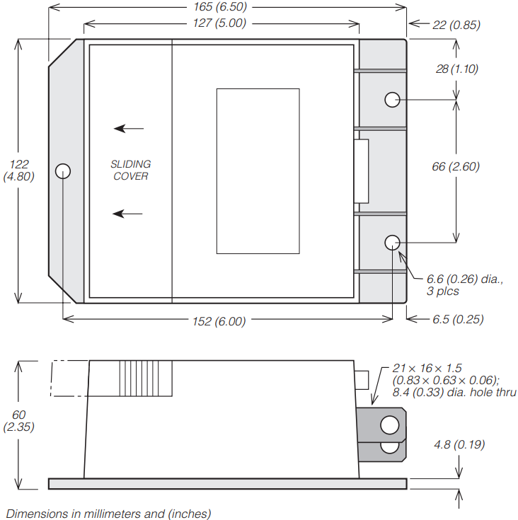
This controller operates at a frequency of 15 kHz, making it a noiseless and cost-efficient choice of controller for permanent magnet DC (PMDC) motors for mobility aid vehicles and AGVs, among others. It has nominal voltage options of 24 volts, 36 volts, and 48 volts and current limit options ranging from 100-200 amperes. It weighs 1.13 kg and is 165 mm in length, 122 mm in width, and 60 mm in depth. The Curtis Model 1213 provides a better driving experience due to key features and optional features such as high pedal disable, IR compensation, ISO fault detection, and brake light driver.


The Curtis 1213 controllers can now be purchased here in Cloud Electric, your one-stop shop for all your electric component needs. Cloud Electric is a leading distributor of electronic components in North America. We take pride in our informative product descriptions, pricing, and shipping speed.

Sort By:
1
Curtis 24V 200A PM Motor Controller 1213-2102 Curtis 24V 150A PM Motor Controller 1213-2101 Curtis 24V 150A WW Motor Controller 1213-2104
Fast Mover - Order today! Fast Mover - Order today! Fast Mover - Order today!
Curtis 24V 200A PM Motor Controller 1213-5101
Fast Mover - Order today!
   
 
1

SPECIFICATIONS

VOLTAGE


  • Nominal Voltage Range

24 V, 36 V, 48 V

  • Operational Voltage (Max)

24 V Model: 30 V

36 V Model: 45 V

48 V Model: 60 V

  • Cutoff (Overvoltage)

24 V Model: 42 V

36 V Model: 48 V

48 V Model: 64 V

  • Cutoff (Undervoltage)

24 V Model: 16 V

36 V Model: 26 V

48 V Model: 35 V

OPERATING FREQUENCY

15 kHz

THROTTLE TYPES

single-ended, center-off (wig-wag), voltage throttle

CURRENT


  • Current Rating Range at 1m

100-200 A

  • Standby Current

150 mA at 24 V


PHYSICAL SPECIFICATION

WEIGHT

1.13 kg

DIMENSION

  • Length

165 mm

  • Width

122 mm

  • Depth

60 mm

PACKAGING

IP54 with boots

IP40 without boots


FEATURES

Feature

Purpose

Brake Control and Variable Drive Speed

Allows accurate vehicle control for an improved driving experience

Full Bridge Power MOSFET

Highly efficient and noiseless operation

Current Limiting

Protects circuitry

Potentiometer

Acceleration and deceleration rates and reversing speed are fully modifiable

Anti-Rollback

A safety function that guarantees no unintentional mobilization will occur

Missing Brake Detection

Restricts the controller once the brake is detected to have an open circuit

Brake Driver (Current-Limited)

Controller is protected from shorts on the brake and wiring

Cutback Function (Undervoltage)

Provides protection from low battery voltage (internal and/or external)

Polarity Protection

Protects the controller by remaining off when the battery wire is reversed due to installation

Neutral Throttle

When the vehicle is off and unmanned, it brakes motor

Push

Allows vehicle to be moved even with the key at off position with limited speed to protect the motor from being shorted

Easy Installation

No further alterations

Plating (Bus Bars)

Protection for solid copper bus bars


OPTIONAL FEATURES

Feature

Purpose

High Pedal Disable

Allows a safe start by monitoring the status of the throttle. If the vehicle is started with an applied throttle, this feature disables it from operating until the throttle is returned to a neutral position

IR Compensation

Allows the vehicle to be at a stable speed when going up or downhill

ISO Pot Fault

Detects open or shorted internal components and protects the system

Brake Light Driver

Powers brake light when decelerating following the engagement with the electromagnetic (EM) brake


DIMENSIONS


WIRING DIAGRAM